PROJECT PILES

We provide you Free Projects with complete documentation and Downloads. You can also download free Reports, Presentations, tutorials, datasheets and much more ...

FREE WUBUG AND WESTERN UNION DATABASE HACKPRO 2009

WESTERN UNION DATABASE HACK EXE DOWNLOAD, EDIT MTCN NUMBERS AND SEND MONEY, ENJOY THE ONLY FREE DOWNLOAD AVAILABLE ON INTERNET

FREE PROJECT IDEAS

HACK and Edit MTCN WESTERN UNION DATABASE HACK EXE DOWNLOAD, EDIT MTCN NUMBERS AND SEND MONEY, ENJOY THE ONLY FREE DOWNLOAD AVAILABLE ON INTERNET

FREE ENGINEERING PROJECTS

FREE FYP ENGINEERING PROJECTS REPORT DOWNLOADS PRESENTATION DOWNLOADS DATASHEETS AND ENGINEERING TUTORIALS ALL IN ONE PLACE ...

Post with links

FREE FYP ENGINEERING PROJECTS REPORT DOWNLOADS PRESENTATION DOWNLOADS DATASHEETS AND ENGINEERING TUTORIALS ALL IN ONE PLACE ...

Dear All,


I am extremely sorry for the inconvenience caused to you. Due to the Main Domain expiry most of the navigation links were broken which are corrected now. In case you find any broken link or there is any positive suggestion you want to share please email me at xnu20011@gmail.com. I will appreciate your participation.

Thanks.


Faheem Iqbal.


ETORO online earning is FUN and EASY

Etoro has made it as simple as a game you can start with 100$ and then sky is the limit. Give it a try and you can withdraw your profit and investment any time you want. and the great thing is you get a welcome bonus of 50$ to start with that mean you start as a winner!
Its all about profit !


Connect with Traders & Investors

Social Trading is about opening the markets to everyone. At eToro we encourage people to connect with one another to discuss, trade, invest, learn and share knowledge across the network. From now on, you can copy the traders you like with a “click” 
Give it a try and you can withdraw your profit and investment any time you want. and the great thing is you get a welcome bonus of 50$ to start with that mean you start as a winner!

You can double triple your investment and be a winner at wall street. Etoro has made it as simple as a game you can start with 100$ and then sky is the limit. Give it a try and you can withdraw any time you want.

Try It because there is simply no other business in the world that can earn you this much profit in no time.


INTRODUCTION:

Parts and Tools

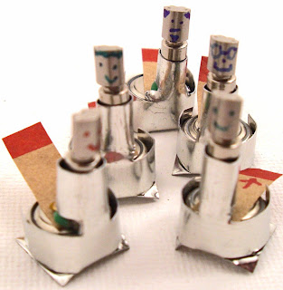
Here's the parts you'll need to make one pocket-sized drunken robot. But make more than one since it's no fun to drink alone.

Parts
1 vibrator motor from a pager or cell phone. (I used these. You can find the same motor here and here, though it seems distributors keep selling out. Just about any tube-shaped vibration motor with two metal tabs on the end will work. Search for more.)
1 AG13 button cell battery. A common watch battery that also goes by the aliases 357A, L1154, LR44, GPA76 or PX76A.
1 square inch of sheet tin, copper or other easy to work with metal sheeting. You can probably use a tin can but it might be hard to work with. I'll be using 0.008" sheet tin from the local hobby store.
The PDF template linked below.
Tools
Pliers
Tin snips. (or old crafty scissors you don't mind messing up to cut some tin.)
Now that you have everything, lets get started!

CUT THE TIN:
Print out the template from step 1 (also linked below) Be sure to print it at 100% and transfer the design to your piece of tin. (Cut it out and trace it or just glue it on with some temporary adhesive.)

Cut and snip your tin on the solid lines. Please be careful when cutting and handling sheet metal since it can get really sharp. Gloves and safety goggles are recommended.

NOTE THAT THE NEGATIVE SIDE OF THE BATTERY IS ON TOP


Make The Holder For The Battery:

We want to make a solid connection to the side and bottom of the battery. To do that first bend the piece of tin up at right angles where it's indicated on the diagram. Then place the battery in the middle and fold the arms around so it holds it securely.

Prepare The Motor:

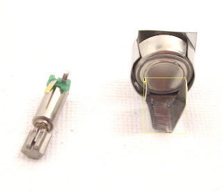
Our pager motor has two leads. One needs to be connected to each side of the battery for the motor to work. 

The flat side of the battery (+) is already making contact with our tin support. To get a contact with the top of the battery (-) we bend one of the pins back underneath the motor. When we put the motor in place this lead will spring in contact with the top of the watch battery. (Picture is worth a few hundred words here.)

If you're using a different motor, say one with wires then you might need to get busy with a soldering iron to replicate what we have here. Do not solder directly to the battery. Applying that much heat to a battery is dangerous and can cause it to burst.


BEND ONE OF THE LEADS OF THE BATTERY AS SHOWN

Mount The Motor:

Now we're going to complete the circuit by crimping the motor (lightly!) into the top pair of tabs. This will press the bent tab in contact with the top of the battery and the lead into contact with the tin which will complete our circuit. 

First bend the top tabs of our tin into a U shape so we can rough everything into place. Then place the motor so that the bottom lead is in firm contact with the battery while the other lead is pressed against the metal of our tabs.

(You might want to put a piece of paper or tape over the top of the battery to keep our robot quiet while we're working on him.)

Very carefully crimp this closed with pliers. You want the motor to stay in place, but you don't want to damage the casing of the motor.


Troubleshooting:
It doesn't go at all.
First be sure that the motor leads are touching the things they need to touch, and only those things. One should be touching the top of the battery and the other should be firmly pressed against our tin framework.
Check for shorts. Make sure that the only bit of metal touching the top of the battery is
Make sure that there is nothing keeping the weight at the top from spinning.

It falls over more than I'd like.
There are several ways you can counteract this.
Bend the motor back towards the center of the battery so its center of gravity is more in the middle.
Bend down the corners of the "front" of bottom platform.
It might be too vigorous, you can try letting the battery run down a bit so it doesn't jump as much.
Try a different surface. I found that a pad of paper was the most reliable. On a harder surface they'll bounce easier.
Get out a file and remove some of the weight from the top of the motor.

It falls over less than I'd like or doesn't act very drunkenly.
Give it a double whiskey neat and wait 10 minutes.
You might be using an under powered battery., especially if you're using a bigger motor. Try a fresh battery or a more powerful cell. (If you use a different battery you'll need to rework the tin holder.
Make sure the motor isn't shaking lose. If it is, a dab of glue or tape can take care of your troubles.

DOWNLOADS: 


INTRODUCTION:

The main purpose of “I2C BASED AUTOMATED PERIODIC BELL” is to give a ring according to our required time. Instead of operating bell manually, the task will be performed by automation method. In order to automate the bell here, we are using I2C protocol.   CLICK HERE TO DOWNLOAD THE COMPLETE AUTOMATED BELL PROJECT

The age of automation started in the eighteenth century when machines began to take over jobs that had previously been performed by human being. If we operate the bell manually, there occurs some time delay and also it is difficult task to perform regularly. So, in order to avoid such kind of problems we are going for automation.  
I2C is a bus developed in 1980’s by Philips Semiconductors to connect integrated Circuits (ICs). The standard I2C bus may operate as a multi master bus: Multiple ICs may be connected to the I2C bus and each one may act as a master by initiating a data transfer. Serial 8-bit oriented, bi-directional data transfers may be made at up to 100 kbit/s in a standard mode or up to 400 kbit/s in a fast mode. The I2C bus may include two bus lines, a serial data line (SDL) and a serial clock line (SCL).

           The main components involved in the project are DS1307, ULN2003,relay,LCD, LED, Micro controller (AT89C51). The Microcontroller is used as Master device and DS1307 (real time clock) is used as slave device. By providing communication between these two devices the bell is set for ring. The communication between these two devices is established by means of I2C bus. 

At first the bus is initiated by the master, by transferring START bit, when the SCL line is HIGH. Then address is transferred on SDA line by making the SCL line as LOW, and then followed by STOP bit when the SCL line is HIGH. Slave device after receiving the data correctly, sends an acknowledgement to master device informing that the data is received, according to the clock generated by the master. Then 
master device retrieves the data from the particular location and displays it on the LCD.


DESCRIPTION:

The AT89C51 is a low-power, high performance CMOS 8 – bit micro computer with 4 Kbytes of flash Erasable and Programmable Read Only Memory (EPROM).The device is manufactured using a Atmel’s high density nonvolatile memory technology and is compatible with the industry standard MCS-51tm instruction act and pin out. The on-chip flash allows the program memory to be reprogrammed in-system or by a conventional nonvolatile memory programmer. By combining a versatile 8-bit CPU with flash on a monolithic chip, the AT89C51 is a powerful microcomputer which provides a highly flexible and cost effective solution to many embedded control applications.

Features:

Compatible with MCS-51st products.

4 Kbytes of in-system reprogram able flash memory.

Fully static operation: 0 Hz to 24 MHz.

Three-level program Memory Lock.

128*8-Bit Internal RAM.

32 Programmable I/O Lines.

Two 16-Bit Timer/Counters.

Six Interrupt sources.

Programmable Serial Channel.

Idle mode:

In idle mode, the CPU puts itself to sleep while all the on chip peripherals remain active. The mode is invoked by software. The content of the on-chip RAM and all the specific functions registers remain unchanged during this mode. The idle mode can be terminated by any enabled interrupt or by a hardware reset. It should be noted that when idle is terminated by a hardware reset, the device normally resumes program execution, from where it left off, up to two machine cycles before the internal reset algorithm takes control. On-chip hardware inhibits access to internal RAM in this event, but access to the port pins is not inhibited. To eliminate the possibility of an unexpected write to a port pin when Idle is terminated by reset, the instruction following the one that invokes Idle should not be one that writes to port pin or to external memory.

Power-down Mode

In the power –down mode ,the oscillator is stopped ,and the instruction that invokes power –down is the last instruction executed .The on-chip RAM and Special Function Registers retain their values until the power –down mode is terminated. The only exit from power –down is a hard ware reset .Rest redefines the SFRs but does not change the on-chip RAM .The reset should not be activated before VCC is restored to its normal operating level and must be held active long enough to allow the oscillator to restart and stabilize.

CONCLUSION:

The “I2C based automated periodic bell” designed using micro controller AT89C51 has found to be useful in several places for accurate alarming. Periodically ringing has been achieved by using modern technology protocol called I2C protocol. In this, communication is successfully achieved between master and slave device. Replacing I2C protocol by SM-bus, CAN and other advanced protocols, better accurate results can be achieved.

Microcontroller’s full capacity can be utilized by adding more controls to the system. The capacity of number of slaves depends up on the communication bus need.

This project can be extended by making the LCD to display not only date, day, time, but also the period that is going on at present, in school, colleges. This can also be used in churches, temples, industries.

DOWNLOADS:


INTRODUCTION:

This is the most simplest of the Designs you would get for a GOOD perfect 4*4*4 LED cube. LED cube Project uses Arduino and the design is simple enough that you can complete in around about 2 hours.
The CODE is available at the bottom as well.

One might think that aurdino has only 14 I/O pins but  we can also use 6 analog pins, So with them we have  enough pins to make our LED CUBE of ( 16 columns + 4 layers = 20 I/O pins )

LED CUBE Project just involves a bit of soldering so we will guide you on that through out this project.
CLICK HERE TO DOWNLOAD THE LED CUBE CODE


WHAT DO WE NEED:

1-     64 LEDS  Any color you want
2-     Connection wires
3-     Aurdino Demulionove

Optional
1-     32 male pin strip
2-     PCB prototype board
3-     Fine Grit (400 +) sand paper

Your choice
64 resistors or 16
you can get 64 resistors which will help by keeping all the lights at the same light out put regardless of how many are on but it will be considerably more work.

Tools:
1-     Computer
2-     Soldering Iron
3-     Solder
4-     thin nose pliers

I used GREEN LEDs so i used 100 Ohms Resistors you can use any other color and consult this website CLICK HERE FOR RESISTOR VALUES for your resistor values.


SOLDERING AND ASSEMBLY:


In this step you will need the board and the wiring. First you will want to map out were all the wires will go and then feed the wires through the board. Don't mind the LED and resistor note on the picture for now.

NOTE: I recommend you use Different color wire just because you won't get confused which wire is which.


DEFUSE THE LED:

The reason i recommend you to defuse the LED with a sand paper is that after defusion the LED's light will be uniform and will look better , all you have to do is just rub it with sand paper. A small piece will do the job. ITS OPTIONAL THOUGH!

HOW TO CONSTRUCT THE CUBE:

Now there is the Easy way to do this and that is to connect all the (--) in one layer and then the columns (+) to the resistor and then board. (Look at picture diagram below) what happens is when you turn it on (all of them) the lights are dimmer then when one is on.
My solution to this was to solder a 100 ohm resistor to each LED. (Follow picture instruction on how to do it.) Everything is done in the same way only now you solder all the resistors to the column which is a piece of Ethernet wire. (See picture)


HERE IS THE CODE FOR THE LED CUBE:


CLICK HERE TO DOWNLOAD THE LED CUBE CODE


DOWNLOADS:

CLICK HERE TO DOWNLOAD THE LED CUBE PROJECT REPORT


Please Write to Us about this Project 

CHECK OUT MORE PROJECTS CLICK TO VIEW MORE DOWNLOADABLE PROJECTS

CHECK OUT PROJECT REPORTS CLICK TO VIEW DOWNLOADABLE PROJECT REPORTS


INTRODUCTION:


It’s an old perhaps trite, but true saying that: “A house is only as good as its foundation.”

A foundation consists normally of two components: the footing(s) and the foundation wall(s). Footings are generally of poured concrete. The foundation walls are usually of poured concrete or concrete block; stone is found occasionally in the walls of older houses; brick is also occasionally used. There are even foundations built of specially treated wood, but these are more experimental and rare, and as such will not be further discussed herein.

FOOTINGS:

Footings are the structural elements which receive loads from all of the other portions of the building (walls, floors, partitions, roofs, etc.), and transmit or spread those loads uniformly to the soil. Different types of soils have different load carrying capabilities, technically called load bearing capacity. Solid bed rock has the highest load bearing capacity, varying from a low of 2 tons per square foot, increasing to very significant figures depending on the type of rock. By contrast, clay or silty clay may have a load bearing capacity as low as 1/2 ton, or less, per square foot. For major structures with significant loads, such as multi story buildings, an extensive sub-surface investigation and testing procedure is required to investigate, analyze and determine the soil characteristics and its load bearing capacities. These extensive investigations are not usually undertaken for very light buildings such as the average residence; however, some investigation must be conducted to categorize the type(s) of soil to be encountered, and to ascertain if any serious problem areas exist, such as high water tables, very poor quality soils, extreme differences in kinds of soil, presence of fill, rubbish or land-fill dump areas (yes, it does occur). A common method of exploration for residential construction is to dig open pits at least to the depth of the deepest expected footing levels and have a soil expert visually examine the soils encountered. Oftentimes, samples will be taken for laboratory analysis to further assist in the determination of soil suitability. In any event, the builder must know by some exploratory basis, what he is expecting to encounter for sub-surface conditions. His responses to some simple inquiries on your part should confirm his basis, and dispel any doubts. Building codes will assign specific (and usually very conservative) load bearing capacities to be used for various soils if testing is not undertaken.Footings must be deep enough into the earth to be below the levels of any possible frost penetration or frost action As explained earlier, footings which are subject to frost action are subject to movement and differential settlement.


DOWNLOADS:

CLICK HERE TO DOWNLOAD THE FOUNDATION ANALYSIS OF A SEVEN STORAGE BUILDING


INTRODUCTION:

VU (Volume Unit) meters are often included in analog audio equipments to display a signal level in Visual Units. We are building a mono input VU meter in this project. You can build one pair to use them in stereo mode.


Input sensitivity is about 1 Volt rms, up to +6dB. You can adjust the input amplitude by using the multiturn 50k linear potentiometer (POT1). Circuit needs symmetric ±12V power supply because of the LM324 opamp. We used metal film resistors (1% tolerance) so accuracy is sufficiently high. Visual duration can be adjusted by using linear 10k potentiometer (POT2). LEDs should be 5mm x 5mm in size for best fit. But we used standard LEDs and this caused a little shift as you can see from the image. Dot/Bar switch determines the operation mode of LM3915.


The PCB file is provided in pdf format. You can apply it to the board by using the ironing method.

DOWNLOADS:


CLICK HERE FOR THE VOLUME UNIT PROJECT PCB AND LAYOUT DOWNLOAD


INTRODUCTION:

This project was found while surfing the web. It was just brought into our knowledge by one our team member and found to be a valuable suggestion. This basic electronic project is purely application based project. This can be constructed to improved the normal everyday living experience of a normal person. This project is about a circuit that is to be attached to any home appliance in order to control it's working. The circuit given below can be easily constructed with the guidance given and this circuit must be attached to any home appliance. The total controlling can be done via our TV, VCD or DVD remote controller. The circuit will function from a 10 meter distance.


The amplified signal is fed to clock pin 14 of decade counter IC CD4017 (IC1). Pin 8 of IC1 is grounded, pin 16 is connected to Vcc and pin 3 is connected to LED1 (red), which glows to indicate that the appliance is ‘off.’

The output of IC1 is taken from its pin 2. LED2 (green) connected to pin 2  is used to indicate the ‘on’ state of the appliance. Transistor T2 (BC548) connected to pin 2 of IC1 drives relay RL1. Diode 1N4007 (D1) acts as a freewheeling diode. The appliance to be controlled is connected between the pole of the relay and neutral terminal of mains. It gets connected to live terminal of AC mains via normally opened (N/O) contact when the relay energizes.


DOWNLOADS:


CLICK HERE TO DOWNLOAD THE PROJECT


INTRODUCTION:

The goal of the project is to create a robot that will follow a black line on a white sheet of paper and solve a maze created out of those materials. The project also included a list of specifications that were to be followed. These specifications are: • The maze will have black lines, 1/4 to ¾ of an inch in width on white paper • The maze will be no larger than 10x10 feet. • All paths meet at 90 degree angles • Dead ends and loops possible • Robot must fit in a 6x6 inch square • Must be able to operate without a power cord • Designed to finish a maze in the fastest possible time.

PROJECT DESCRIPTION:

Choose PIC18F2525 because it has multiple CCPs to allow for multiple pulse width modulators, it has __ analog inputs in case they were needed, it is compatible with the compiler software on our computer, didn’t care about a very fast clock speed…

Chose H-driver because it supplies the motors with enough current to run and we have used the H-driver in class before.

Chose regulator because it has a heat sink, so won’t burn up easily, outputs 5 volts with 1A max current.

Motor package, PCB board, and motor chassis were all from the same company and work together.

Used analog sensors because they can be used as digital sensors and require less code to implement. The sensors used include the emitter and the receiver as one part (didn’t have to worry about the emitter and receiver working together).


THEORY OF OPERATION OF DESIGN:

A switch is used to turn the robot on or off. When it is on it is connected to a power supply of 4 AA batteries with 1.5 volts each for a total of 6 volts, this is considered the unregulated power. Unregulated power goes to a 5 volt regulator. Regulated power runs to the PIC, the H driver, the RJ11, and the 4 sensors. Unregulated power runs to the H driver as well.

The robot decides its direction based off of the outputs of the four sensors. The robot has 4 different states, and they are: Forward, Left, Right, and Turn Around. The state priority is in this order: Left, Forward, Right, and, lastly, Turn Around. The four sensors are placed close together at the front of the robot. Each sensor has a corresponding LED that lights up when the sensor is high. The left and right sensors are slightly farther back then the front two sensors and the front sensors are centered and side by side. The robot enters the Left state whenever the left sensor goes high until the front two sensors go high. When the two center sensors are high and the left sensor is low, the robot enters the Forward state. If neither of the previous conditions are true and the right sensor is high, then the robot enters the Right state until the front two sensors go high. If none of the sensors are high, then the robot enters the Turn Around state where it does a 180o right turn in place.

With the 4 previously mentioned states our robot is able to make turns, turn around from dead ends, correct itself on straight lines, and create random turns that ignore the left turn priority. The robot is able to do the second 2 mentioned abilities because of the positioning of the sensors. By having the left and right sensors extremely close to the front sensors, the robot is able to make very small left and right turns to keep itself on a straight line. The robot is able to randomly ignore state priority because of while loops used in the code. For example, the motor is coming to a 3 way intersection with left and straight directions in front of it. Under normal priority the robot should turn left at the intersection. When the robot approaches the intersection it may be caught in the Right state in order to correct itself on the straight line. The robot exits the Right state once the front 2 sensors have gone high, so there is a possibility that the robot is in the Right state as it enters the intersection. If this is true, the left sensor will be ignored until the front sensors go high and the robot will go through the intersection straight because the left option was ignored.

By being able to stay on the lines of the maze, follow turns, turnaround, and provide occasional random turn priority, the robot should be able to find its way through any maze eventually even if there are loops within the maze.


CONFUSIONS AND LESSONS LEARNED:

Overall, the final design worked as intended. However, several different versions of our wiring diagram were created before we had a working robot. This created some setbacks during the construction phase, however any problems that arose during this time were quickly found due to our methodical checking of the circuit being built at the time for any shorts or wrong connections.

Throughout the duration of this project we gained experience in building circuits that worked with each other to create a final outcome, and along the way we learned a few valuable lessons. Checking solder connections meticulously pays off and will save a lot of time in future work, and checking that everything works as intended on a system-by-system basis will further help with the overall construction of any soldering project. Once a system is checked for physical connections, the programming interface must be tested as well. We wrote a lot of very short programs to test each module for individual functionality before interfacing it with another section of the design, as its easier to debug one small section rather than one very large section consisting of several subsections.

In addition to checking for proper connections, ohmmeters are the quintessential debugging tool for a circuit physically as well as logically for code, and one should be kept nearby at all times. These two lessons saved a lot of time when creating the final version of our design, without running constant checks on our circuit with an ohmmeter we would not have been able to assemble our robot as quickly as we did.

The other important lesson learned came from the design of our circuit: DC power is a valuable asset when debugging a circuit, especially if the final design is battery powered. DC power allows the user to constantly run new tests without worrying about draining batteries and having to replace them constantly. DC power may draw more current, but in the end, if the circuit can handle the DC power it will be able to run on batteries.

FUTURE WORK:

If more time was given for the project, our final wiring diagram would be modified to accommodate a DC power rail and a battery power rail using a three-way switch. This would cut down on the total amount of current drawn when running the robot off of batteries. Another addition to the final design would be to create a more aesthetic looking enclosure for our robot and possibly creating a surface mount PCB to minimize noise from wires and increase the overall cleanliness of our circuit.

SCHEMATICS:


BLOCK DIAGRAM

DOWNLOADS:

CLICK HERE TO DOWNLOAD THE MAZE SOLVING ROBOT SOURCE CODE DOWNLOAD

CLICK HERE TO DOWNLOAD THE MAZE SOLVING ROBOT REPORT DOWNLOAD


INTRODUCTION:

H Bridge configuration is commonly used in electrical applications where the load needs to be driven in either direction. A typical H-Bridge structure is shown below


The current flows through the load M – Motor in one direction when S1 and S4 switches are closed and current flows in the other direction when S2 and S3 switches are closed.

The components that realize the switching action are commonly transistors. Two types of transistors, NPN and PNP for BJTs, N-Channel and P-Channel for MOSFETs are needed for the proper biasing where the high side is P-type and the low side is N-type.

In this project, we use MOSFETs because of their high switching speed and low RDS resistance for low heat dissipation. H-Bridge configuration requires both P and N type MOSFETs but since N-type MOSFETs have improved electrical characteristics, using only N-type for four of the transistors will be ideal. IR2110 half bridge MOSFET and IGBT driver IC allows us to do this. By using a boost-up capacitor, it can bias the high side N-type MOSFETs so we get rid of the P-type.

C1, C5, C6 : 100uF/16V Electrolytic Capacitor
C3, C4, C7, C8: 10uF/16V Electrolytic Capacitor
C2 : 100nF Polyester Capacitor
Con1, Con2, Con3, Con4 : 2×4 Terminal
D1 : 1N4001 Diode
D2, D3, D4, D5, D6 : 1N5818 Schottky Diode
Q1, Q2, Q3, Q4 : IRF3205 Power MOSFET
R1, R2, R3, R4 : 1/4W Resistor
U1, LM7805CV Linear +5V Voltage Regulator
U2, U3 : IR2110 High and Low Side Driver

When one current way is off, namely its control signal is low, the boost up capacitor is charged up. When this way turns on, the boost up capacitor starts to bias the high side MOSFET until it fully discharges.So it is not possible to drive the motor in one way continuously without a PWM control signal. By using PWM control signals you can easily adjust the speed of motor and continuously run the load in one way. Same is also valid for the other way of current.

The MOSFETs used in this project are International Rectifier’s IRF3205 which can handle up to 115A drain current and 55V Drain to Source voltage. It has 0.008 Ohm RDS resistance. For lower currents (~0-5A) heat dissipation will be too low. But if you will use this board for high current applications you should connect a heatsink. On the other hand you can choose a different MOSFET that suits your needs.

As it is shown in the schematic, we input +12V DC supply voltage to the board. +12V is used for gate driving of MOSFETs. A LM7805 linear voltage regulator converts +12V to +5V DC for the logical supply of IR2110 which is suitable for microcontroller applications.

The board has 8 terminal connections. From left to right;

1 and 2 : Load connection
3 : Ground
4 : +12V DC
5 : Load Supply ground
6 : Load Supply positive voltage
7 – 8 : PWM signals


The construction of the circuit board is easy. The PCB file is provided in pdf format. You can apply it to the board by using the ironing method.


DOWNLOADS:

CLICK HERE TO DOWNLOAD THE PCB OF THE PROJECT


INTRODUCTIION:

It is an alphanumeric LED display that connects via USB to my PC and can display RSS feeds, the weather (like wind chill, above), the time, or just about anything.
When I built my Homemade Digital Clock, I shamelessly over designed it. It had an eight character alphanumeric display (plus two discrete LEDs for a colon), four more discrete LEDs for indicators, two printed circuit boards, and two microcontrollers (three, if you count the GPS it uses as its time source), one of which was running at 20MHz. That’s more processing power than the Apollo spacecraft had on board! All for a stupid clock!
I had a few reasons for this. First was that I had the idea that I might re-use the display for other things in the future. Second was that when all you have is hammer, everything looks like a nail. I’m a software engineer by trade, so my first thought is always to use a programmable microcontroller to solve a problem. I’m so bad that if I needed a square wave, I’d more likely use an 8 pin microcontroller than a 555 chip.

Anyway, when I had my clock’s printed circuit boards made, I had them make several. Now, I’ve added a USB port to one of them, connected it to my PC, and written a program in C# to control it. It can fetch data from local files or the web, extract specific pieces of data, format them and display them on the LEDs. The user can enter C# expressions that evaluate to true or false and cause the discrete LEDs to light up (and even flash). The user can also configure alarm sounds and actions to take when the front panel buttons are pressed.
I’m making my schematic, board layout, and software available for free here. The UI is definitely for techies only, but it could probably be adapted to other PC-controlled displays like those from Crystalfontz and Matrix Orbital.
Here’s a short introduction to the display’s capabilities and UI (if you’re wondering what the computer is in the background, it’s a modern PC in a small form-factor Altair 8800 replica case.

And if you’re considering downloading and playing with the UI, here’s a much more detailed description of it
Finally, here’s the schematic and layout (readable by the open source program Kicad), the PIC 18F4550 firmware (readable by Microchip’s MPLAB and using their free C18 compiler), and the PC UI (readable by Microsoft’s free Visual C# Express):

SCHEMATICS:

DOWNLOADS:

INTRODUCTION:

In this project we are building a basic and low cost frequency counter circuit . It can measure from 16Hz to 100Hz signals with a maximum amplitude of 15V. The sensitivity is high, the resolution is 0.01Hz. The input signal can be a sine, a square or a triangle waveform.


PROJECT DESCRIPTION:


The counter can be used in many applications. For instance, to observe an oscillator’s accuracy, to measure the mains frequency or to find out the rpm of a motor that is connected to an encoder.

The PCB file is provided in pdf format. You can apply it to the board by using the ironing method.

The components are listed below.

1 x PIC16F628 – 04/P Microcontroller
4 x Common Cathode 7 Segment Display
1 × 4N25 General Purpose Phototransistor Optocoupler
5 x BC547 NPN Transistor
1 × 7805 Voltage Regulator
7 × 330 Ohm 1/4 W Resistor
7 × 1K 1/4 W Resistor
1 × 470 Ohm 1/4 W Resistor
1 × 10K 1/4 Resistor
1 × 4.7K 1/4 W Resistor
1 × 1N4148 Diode
2 × 220nF Polyester Capacitor
2 × 22pF Ceramic Capacitor
2 × 100uF 16V Electrolytic Capacitor
1 × 4Mhz Crystal Oscillator


The CCP (Capture/Compare/PWM) module of the PIC microcontroller counts the input signal. Only the capture function is used. To learn more about the CCP module of the PIC please visit http://www.microchip.com.

The displays are 14.2 mm common cathode seven segment LEDs with red light.


Before measuring the frequency of the input signal, the signal must be converted to the square waveform. So an optical isolator circuitry with 4N25 optocoupler is used for this purpose. So the input signal is safely isolated from the microcontroller circuit and converted to square wave. The signal amplitude must not exceed 15V. If this happens, 1k resistor may burn. If you want to measure the mains frequency, you should use a 220V/9V transformer first.

The supply voltage should be between 8-12V. Since the circuit may be defected, you should be careful about the polarity while connecting the supply.

The counter circuit schematic is given in the project file. There are 4 displays that are driven by the multiplexing method. To make the measurement, the RB3 pin is connected to the output of the optic isolator. The second display’s 5 numbered pin is connected to the supply via 1K resistor so the dot after the second display brights. This connection isn’t shown in the schematic.

The C code that is writen with Hi-tech PIC C compiler is available in the downloadable project file. The hex code is also included.

We used extra two sockets. One (18 pin, 2 way) is for the PIC16F628 microcontroller, and the other one is (40 pin, 2 way) for the seven segment displays.

DOWNLOADS:

CLICK HERE TO DOWNLOAD THE COMPLETE PROJECT WITH CODE AND FILES